Get Started With Axiom Board
To Start Using the Axiom Board you need to follow 3 easy steps: Basic Setup, Flash MicroSD Card and Insert & Power Up.

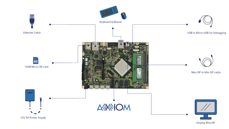
STEP 1
BASIC SETUP

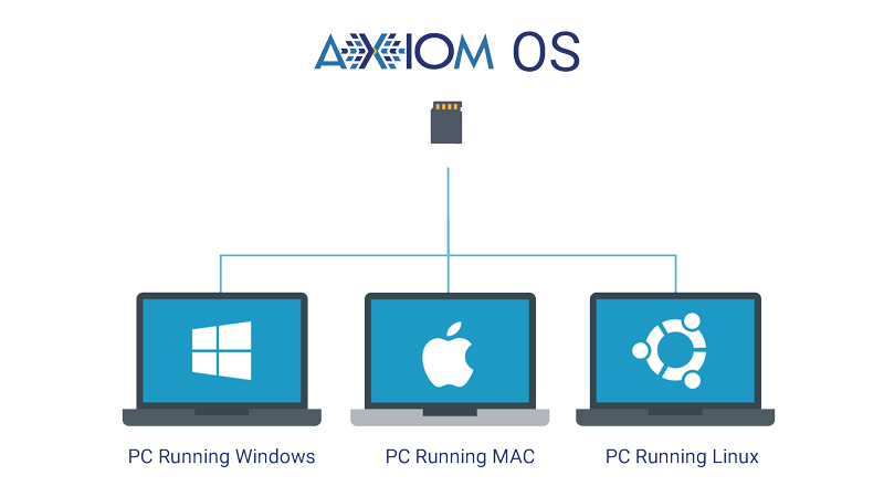
STEP 2
FLASH THE MICRO SD CARD
The second step will guide you through the creation of a bootable Micro SD card for the AXIOM Board, starting from a precompiled image file containing the AXIOM OS.
First, simply unzip the image and write it on the Micro SD card using the dd tool for UNIX/MAC users or Win32DiskImager for Windows users. It is not possible to create a bootable Micro SD card with drag and drop.

SD CARD REQUIREMENTS
Please consider that the size of a Micro SD card must be at least 16GB; Micro SD memory cards with a higher capacity may be used, and the Linux root partition will be expanded to the full SD card size during the first boot.
STEP BY STEP GUIDE
- Download the official Micro SD image from here. To check out all the versions please follow this link.
- Extract the .img file from the .tar.bz2 file you downloaded into any folder (this path will be referred to as <img_file_path> in the guide).
- Follow the instructions below for the OS you have in your computer:
Extract the downloaded zip file, so you’ll have a .img image file. Do not use the preinstalled archive extractor, use 7-zip or similar to decompress the zip file.
Download the Win32DiskImager software and unzip it.
If your PC has a slot for SD cards (you may need a Micro SD to SD adapter), simply insert the card. If not, insert the card into any SD card reader and then connect it to the PC.
Run the file named Win32DiskImager.exe right-clicking it and selecting “Run as administrator”.
If the Micro SD card (Device) used is not detected automatically, click on the drop down box on the right and select the identifier of the Micro SD card that has been plugged in (e.g. [H:]). If your Micro SD card is not listed, try to format it using the FAT32 file system.
Heads up! Please be careful to select the correct drive identifier; if you use the wrong identifier you may lose all data in your PC!
In the Image File box, choose the downloaded .img file and click “Write”. Click yes in case a warning message pops up.
The Micro SD card is now ready to be used. Simply insert it in the board’s Micro SD Card slot and boot the system.
From the Terminal app run
df -h
If your Mac has a slot for SD cards (you may need a Micro SD to SD adapter), simply insert the card. If not, insert the card into any SD card reader and then connect it to the Mac.
Run again
df -h
The device that wasn’t listed before is the Micro SD card just inserted. The name shown will be the one of the filesystem’s partition, for example, /dev/disk3s1. Now consider the raw device name for using the entire disk, by omitting the final s1 and replacing disk with rdisk (considering the previous example, use rdisk3, not disk3 nor rdisk3s1).
Heads up! Please be careful to select the correct device identifier; if you use the wrong identifier you may lose all data in your Mac!
Unmount all the partitions in the SD card (use the correct name found previously, followed by letters and numbers that identify the partitions). using diskutil:
sudo diskutil unmount /dev/disk3s1
Now write the image on the Micro SD card using the command:
sudo dd bs=1m if= of=/dev/
Please make sure that you replaced the argument of input file (if=) with the path to the .img file, and that the device name specified in output file’s argument (of=/dev/) is correct. Please also make sure that the device name is the one of the whole Micro SD card as described above, not just a partition (for example, rdisk3, not disk3s1). For example:
sudo dd bs=1m if=/Users/YourName/Download/udoo-neo-udoobuntu.img of=/dev/rdisk3
Once dd has been completed, run:
sudo sync
sudo diskutil eject /dev/rdisk3
The Micro SD card is now ready to be used. Simply insert it in the board’s Micro SD Card slot and boot the system.
From the terminal run
df -h
If your PC has a slot for SD cards (you may need a Micro SD to SD adapter), simply insert the card. If not, insert the card into any SD card reader and then connect it to the PC.
Run again
df -h
The device that wasn’t listed before is the Micro SD card just inserted. The left column will show the device name assigned to the Micro SD card. It will have a name similar to /dev/mmcblk0p1 or /dev/sdd1. The last part of the name (p1 or 1, respectively) is the partition number, but it is necessary to write on the whole Micro SD card, not only on one partition. Therefore, it is necessary to remove that part from the name (for example /dev/mmcblk0 or /dev/sdd) in order to work with the whole Micro SD card.
Heads up! Please be careful to select the correct device identifier; if you use the wrong identifier you may lose all data in your PC!
Unmount all the partitions in the SD card (use the correct name found previously, followed by letters and numbers that identify the partitions). using umount:
sudo umount /dev/sdd1
Now write the image on the Micro SD card using the command:
sudo dd bs=1M if= of=/dev/
Please make sure that you replaced the argument of input file (if=) with the path to the .img file, and that the device name specified in output file’s argument (of=/dev/) is correct. For example:
sudo dd bs=1m if=/home/YourName/Download/udoo-neo-udoobuntu.img of=/dev/rdisk3
Once dd has been completed, run:
sudo sync
The Micro SD card is now ready to be used. Simply insert it in the board’s Micro SD Card slot and boot the system.
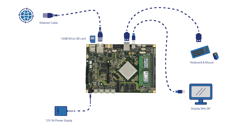
STEP 3
INSERT MICRO SD AND POWER UP
BASIC TUTORIAL
BLINKING LED
In this tutorial we’re going to learn how to write, upload and execute your first Arduino-compatible sketch on AXIOM Board.
In nerd’s jargon this is usually referred as “Hello World”, aka the first basic command you give to a device. Our “Hello World” will be a blinking led, simple as it sounds. So, let’s get our hands dirty.
STEP BY STEP GUIDE
In AXIOM OS desktop:
- Open the Arduino IDE, you can find it in: applications>programming>Arduino IDE;
- Select the right Board from Tools>Board>AXIOM AVR8 IP;
- IF you want just try the code go to: Files>Examples>01.Basics>Blink;
- Then Verify and Upload the Sketch;
- Otherwise IF you want some advantage knowledge follow all the steps below to understand the code better.
UNDERSTANDING THE CODE
Every Arduino sketch contains 2 parts that are absolutely needed:
void setup()
This comes at the beginning, insert here environment values
void loop()
Here you put your main code, to be executed repeatedly. The code must be contained between
Let's insert the proper code now:
First we're gonna name our pin, that is purely for future convenience. Since we got our LED connected to pin 13, we call pin 13 led
int led = 13;
then we configure our pin as an output
void setup()
Ok, now the real code!
Let's turn on the LED, to do so we set the pin led to HIGH state:
digitalWrite(led, HIGH);
void loop()
The complete sketch will look like this:
int led = 13;
void setup()
void loop()
To execute this command, let's upload this, to do so:
- It's a good practice to give your code a second look, just to spot some typos or logic errors;
- When you're sure everything is fine, click on Verify. This will check your code, or Sketch, for errors;
- If everything is fine, cross your fingers and hit upload;
- After few seconds, when your code has done being loaded, magic will happen. The LED will lit!
Ok, now that you're initiated to Pin state mode, let's push things forward.
To turn it off, just set his value to off:
digitalWrite(led, LOW);
The complete sketch will look like this:
int led = 13;
void setup()
void loop()
Ok, now we know how to turn the LED on and off. What about using these 2 states combined to have a blinking LED? The logic behind this is that we turn the state HIGH, then we keep this state for some time and then we set it to LOW, keep this some time again and restart. To ensure that our led blinks and doesn't just lit on and off, we set these logical states into a loop, that will repeat these actions forever (or, until we stop it).
void loop()
Then wait another second, and restart the loop, so the LED will turn on again.
Our final sketch
int led = 13;
void setup()
void loop()
Verify and upload this sketch as you did before and enjoy your blinking LED.